SOB IP68 Waterproof LED Strip: Extruded Silicone Construction
By DENO LED Lighting ·
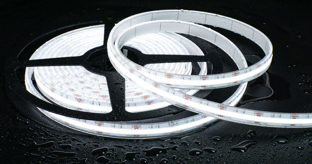
See how DENO builds SOB IP68 waterproof LED strips with individually packaged LEDs, an extruded silicone body and sealed end terminations.
A DENO SOB IP68 waterproof LED strip combines individually packaged LEDs with an extruded silicone body and sealed end terminations. The extrusion forms the flexible outer enclosure; the cable entry and closed end complete the sealing system around the finished assembly.
This construction matters because water protection depends on the whole assembly, not the strip body alone. The selected model, factory termination, immersion conditions, mounting detail and electrical design must therefore be reviewed together before a project is approved.
How DENO SOB construction differs from COB
SOB means Solder-on-Board. DENO SOB strips use individually encapsulated, gold-wire-bonded LED packages soldered to the FPCB, with a continuous silicone optical layer creating the uninterrupted luminous line. This is different from COB construction, which mounts bare flip-chip dies directly on the board beneath a shared phosphor layer.
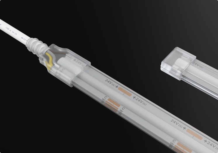
The IP20 and IP68 versions below help show the change from an exposed strip assembly to a silicone-enclosed product. They are construction illustrations, not dimensional drawings or evidence of electrical performance.


How silicone extrusion and sealed terminations work together
The continuous silicone extrusion forms the flexible outer profile around the SOB strip. At each end, the cable entry or closed termination introduces another interface that must remain compatible with the body and the intended environment.
A suitable enclosure can still lose protection if a termination is cut, damaged, pulled or resealed with an unapproved method. For project orders, factory-finished lengths and confirmed cable-exit positions can reduce field work at these interfaces. This does not make every installation identical: the approved assembly process and checks must match the selected product.
What IP67 and IP68 do—and do not—establish
Under IEC 60529, IPX7 and IPX8 address immersion under defined test conditions. IPX8 conditions—including depth, duration and the tested assembly—must be specified and agreed for the product. The designation should not be read as unlimited immersion at any depth or for any duration.
The higher immersion numeral also does not automatically prove that a product has passed the separate IPX5 or IPX6 water-jet tests. Wash-down, high-pressure cleaning, salt water, chlorinated water, oils, solvents and other chemicals require their own suitability review. Where a project needs both immersion and water-jet resistance, request the relevant documented ratings and test conditions for the complete finished assembly.
The BEAMA Guide to IP Codes provides a practical explanation of the scope of IP classifications.
Handling, bending and mounting
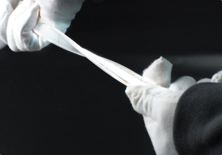
Flexibility allows the strip to follow its permitted curve, but it does not allow unrestricted bending, folding or twisting. Confirm the allowed bend direction and minimum bend radius for the exact profile. Avoid sharp folds, tension at the cable entry and loads transferred through the termination.
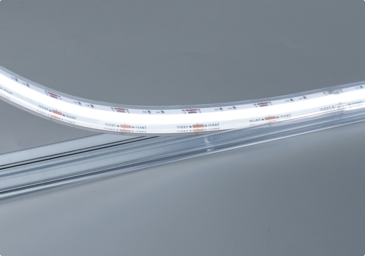
The clear PC mounting channel shown below supports alignment and retention. It is not the waterproof enclosure and should not be described as an aluminium heat sink. Channel fit, support spacing and thermal requirements must be confirmed for the selected strip and installation detail.
Specify the finished lighting system
The visible light line is only one part of the specification. Electrical, optical, mechanical and environmental requirements vary by model and project. Review a sample in the intended mounting detail and request data for the finished waterproof configuration where available.
| Project item | What to confirm before ordering |
|---|---|
| Product identity | Exact model, finished profile and approved application |
| Electrical design | Supply voltage, power per metre, driver/control compatibility, cable size and feed layout |
| Optical performance | CCT, CRI, colour tolerance and light output for the selected waterproof configuration |
| Mechanical installation | Cut unit, finished length, bend direction, minimum radius, channel fit and cable-exit position |
| Water protection | Documented IP test conditions for the complete assembly, including both terminations |
| Site environment | Expected immersion, water jets, chemicals, UV exposure, temperature and maintenance method |
Do not apply a universal run length or cutting interval to the series. DENO SOB models use different circuit layouts and cut units. The permitted length depends on voltage, power, conductor geometry, feed method and acceptable voltage drop. Use the selected model data and an approved wiring plan.
Frequently asked questions
Does IP68 mean the strip can remain underwater indefinitely?
No universal duration or depth follows from the label alone. IP68 immersion capability depends on the documented test depth, duration, termination method, complete tested assembly and installation conditions. Obtain confirmation for the exact model and project environment.
Does IP68 automatically include wash-down or water-jet resistance?
No. IPX7/IPX8 immersion tests do not automatically establish IPX5/IPX6 water-jet performance. If both exposures matter, request the relevant documented ratings and conditions.
Can an SOB IP68 strip be cut and resealed on site?
Only at the permitted cut locations and with the manufacturer-approved termination procedure. A field-cut strip does not automatically retain the protection of the original finished assembly. Factory-finished lengths can reduce this risk where practical.
What is the maximum length powered from one end?
There is no single value for every SOB waterproof strip. It depends on the exact model, supply voltage, power, circuit design, cable and acceptable voltage drop. Request a wiring recommendation for the actual project length.
Discuss the application with DENO
Explore the DENO SOB LED strip range, or contact the DENO custom LED strip engineering team.
Share the installation drawing, environment, required finished lengths, cable exits, operating voltage, target light output, CCT, mounting method and quantity. DENO can then review the product configuration, termination arrangement and installation constraints without relying on generic series assumptions.