Factory-Moulded End Caps for Silicone LED Neon Flex
By DENO LED Lighting ·
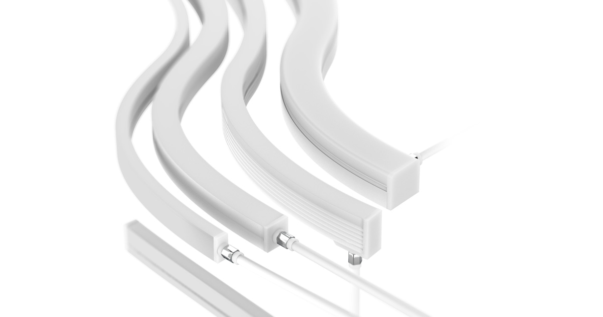
A closer look at factory end-cap forming, low-profile termination design and cable-exit options for silicone LED neon flex.
An outdoor neon flex specification should address the finished ends, not just the silicone body. The interfaces between the body, end cap and cable jacket all need to be considered when designing the seal.
DENO uses machine moulding for the end-cap construction discussed here, rather than fitting a separate end cap and sealing it by hand. This article focuses on that end-finishing process — not on how the full length of the silicone body is manufactured. The objective is a repeatable termination with an end shape matched to the neon profile.
What Is a Factory-Moulded End Cap?
A factory-moulded end cap is formed at the neon flex termination using shaped tooling. The mould defines the outside geometry and supports positioning of the end and cable during forming. This differs from attaching a separately manufactured cap with a manually applied sealant.
The distinction is where and how the termination is formed, not whether people are involved anywhere in production. Preparation, loading and inspection may still require an operator. The specific forming method should also be distinguished from silicone extrusion, which produces the lengthwise body profile.
How the End-Cap Process Works
The following workflow outlines the main stages and control points. Material preparation, forming settings and inspection requirements must match the selected neon profile and cable construction.
1. Prepare the termination
Confirm the required length, permitted cutting position and cable-exit arrangement. Prepare the end and connection area using a procedure compatible with the body and cable materials. Cleanliness and correct positioning matter at the surfaces that will form the seal.
2. Locate the assembly in the mould
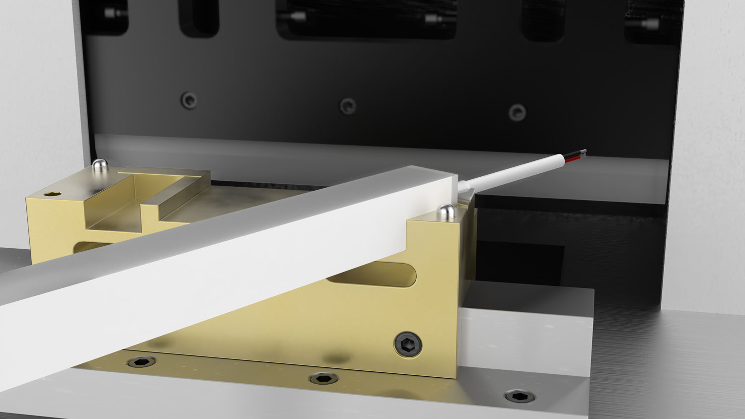
The tooling positions the neon body and, at the powered end, the cable. This establishes the intended end shape and cable location. Proper support also helps prevent the assembly from shifting during forming.
3. Form and cure the silicone
The silicone is formed in the tooling using a process suitable for the selected material. For conventional silicone rubber moulding, curing sets the material; this should not be described as melting and cooling a thermoplastic. Material delivery, air management and curing conditions are relevant controls, but the appropriate settings depend on the actual process. [1][2]
4. Demould and check the finish
Remove the assembly after the required curing stage without damaging the termination. Relevant visual checks include incomplete filling, surface defects, excess material and the transition between the end cap and body. Appearance is useful for inspection, but it does not establish the absence of internal defects or prove an IP rating. [1][3]
5. Verify the finished configuration
The verification plan should address dimensions, the electrical connection, cable retention where applicable, and ingress protection. Evidence should identify the tested construction, including its ends and cable entry. A process illustration or a successful lighting check is not a substitute for sealing-test evidence. [3]
Why Use Moulding Rather Than a Hand-Fitted Cap?
Matched tooling provides a defined shape for the end cap and cable exit. This offers a practical way to control termination geometry instead of relying primarily on manual cap placement and sealant application. A low-profile end can also be designed around the clearances of the intended mounting channel.
However, the silicone body, newly formed end and cable jacket still meet at interfaces that require appropriate material selection and process control. Moulding does not automatically produce chemical adhesion, eliminate every void or make the assembly leak-proof. A properly specified adhesive-bonded cap can also provide effective sealing. [1][2]
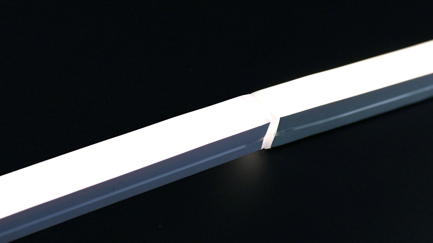
A compact end design can reduce visible bulk at a joint. It should not be presented as a guarantee of an invisible joint or identical brightness through every connection.
Cable Exits and Installation Fit
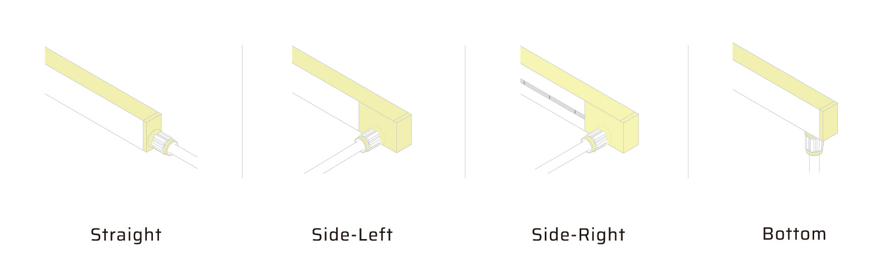
The illustrated options are straight, side-left, side-right and bottom cable exits. Confirm the reference orientation on the product drawing, together with the cable dimensions, available installation space and end-cap envelope.
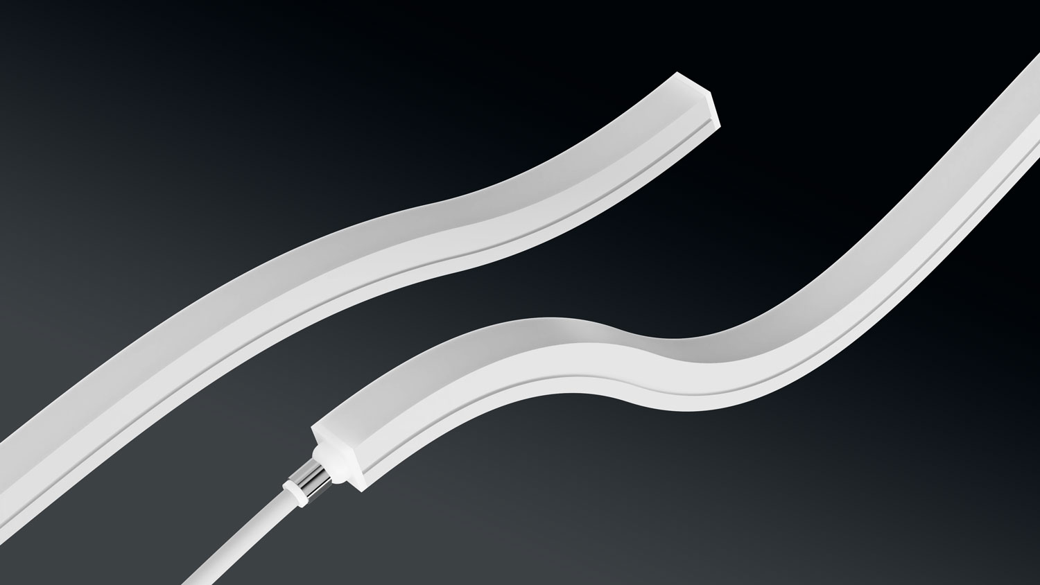
A cable-entry seal and cable retention serve different purposes. Confirm the intended restraint arrangement and avoid loading the entry during installation. An external metal component, by itself, does not establish the sealing performance of the complete assembly.
What Does IP67 Confirm?
IP67 describes dust-tight protection and protection against the effects of temporary immersion under specified test conditions. It is a performance classification, not a manufacturing method. Moulding alone does not assign that rating. [3]
For an IP67 specification, request evidence applicable to the complete terminated configuration. Jet cleaning, continuous immersion and chemical exposure require their own suitability assessment; they should not be inferred from the IP67 label. [3]
Frequently Asked Questions
Can factory-terminated neon flex be cut on site?
Cutting removes the original end termination. Any new termination must follow an approved procedure for that model. Do not assume that applying a general-purpose sealant restores the factory configuration or its documented protection level.
Does a moulded end cap automatically provide a better seal?
It provides a controlled way to form the termination. A comparative sealing claim still requires evidence for the actual materials, geometry and test conditions — not just the name of the process.
Specify Your Neon Flex Termination with DENO
Share the profile, finished lengths, cable-exit direction, mounting arrangement and exposure conditions. DENO can review the required end configuration and confirm the applicable model specification before production.
Explore DENO neon flex · Discuss your custom configuration
Technical References
- Shin-Etsu Chemical — Silicone Rubber for Molding, especially the moulding equipment and defect-control guidance on printed page 22. General process reference, not a DENO test report.
- Protolabs — Designing for Liquid Silicone Rubber. General guidance on curing, tooling and material interfaces; its service-specific conditions are not DENO specifications.
- Intertek — Ingress Protection Testing for Lighting; IEC 60529 publication information. References explain protection categories, not certification of this DENO construction.